
Loading direction and fracture pattern
Read the draft explanation
Start with the load, then follow the stresses.
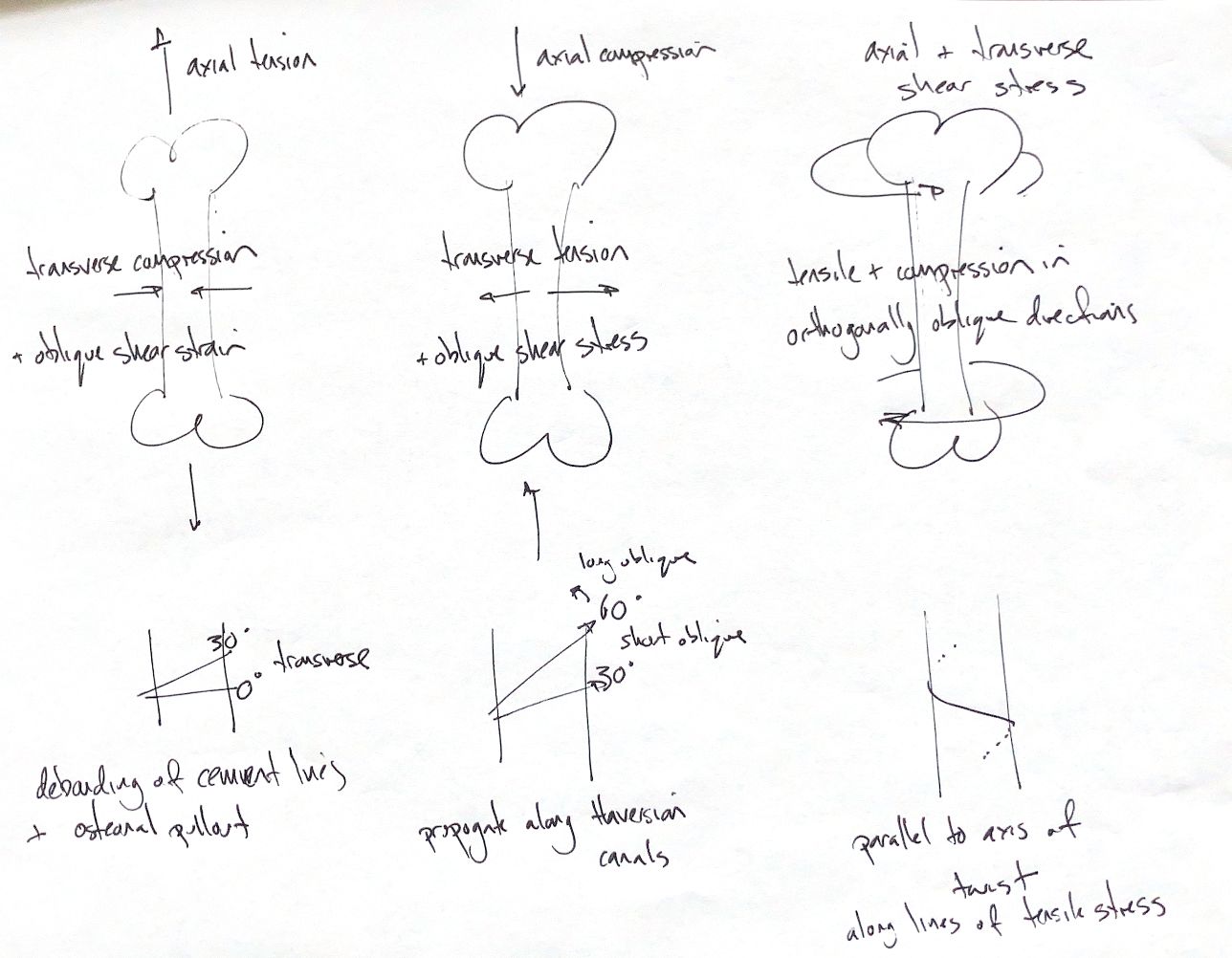
Axial tension pulls the bone apart. It also creates transverse compression and oblique shear. Failure tends to be transverse, with cement-line debonding and osteonal pull-out.
Axial compression pushes the bone ends together. Transverse tension and oblique shear also develop. Shear drives an oblique fracture, with cracks propagating along the Haversian canal system.
Torsion twists the bone around its long axis. It creates axial and transverse shear, plus tension and compression in perpendicular oblique directions. Failure can start parallel to the twist axis, then follow the tensile-stress lines to form a spiral fracture.
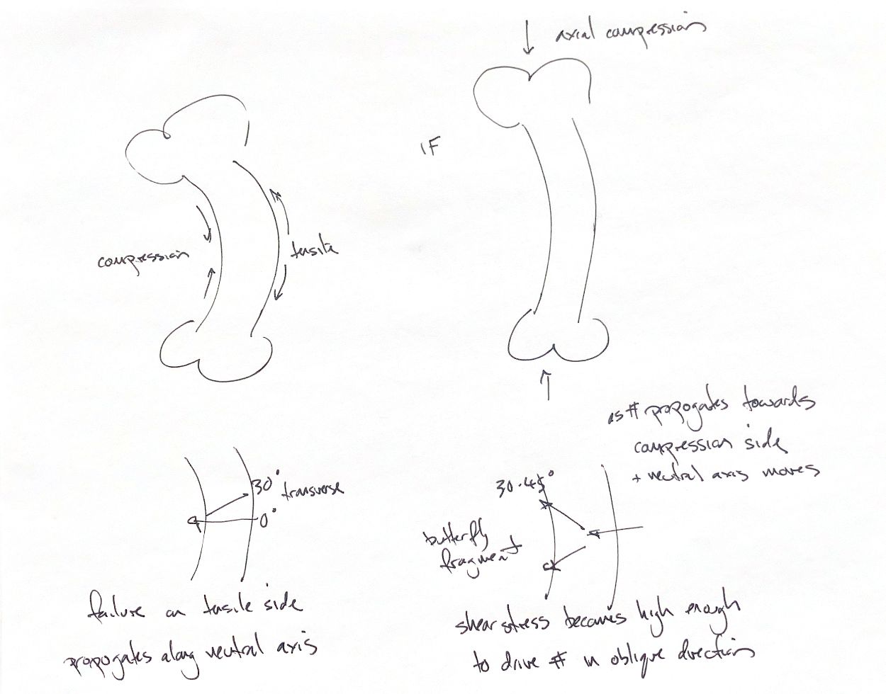
Bending compresses the concave side and stretches the convex side. Between them lies the neutral axis, where longitudinal bending strain is zero. Failure starts on the tensile side and crosses towards the compression side, often transversely or in a short oblique line. It crosses the neutral axis; it does not track along it.
As the crack advances, the neutral axis shifts towards compression. Oblique shear can redirect the crack and form a butterfly fragment on the compression side. Adding axial compression causes buckling and can produce a larger wedge. The 30–45° branching cue is approximate: the idealised shear maximum is about 45° to the neutral axis.
The 0°, 30° and 60° diagrams are angle examples measured from a transverse reference, perpendicular to the bone's long axis. They show increasing obliquity. They are not universal classification cutoffs. Transverse, short oblique and long oblique definitions vary between classification systems, so describe the geometry and name the reference used.
These are simplified loading models. Bone’s response varies with direction, and real injuries often combine several loads.
References
Johnston & Tobias, Veterinary Surgery: Small Animal, 2nd ed., Ch. 39, fracture biomechanics and Figs. 39.33–39.35; Ch. 51, Table 51.2 for an alternative morphology convention.