
Area moment of inertia
Read the draft explanation
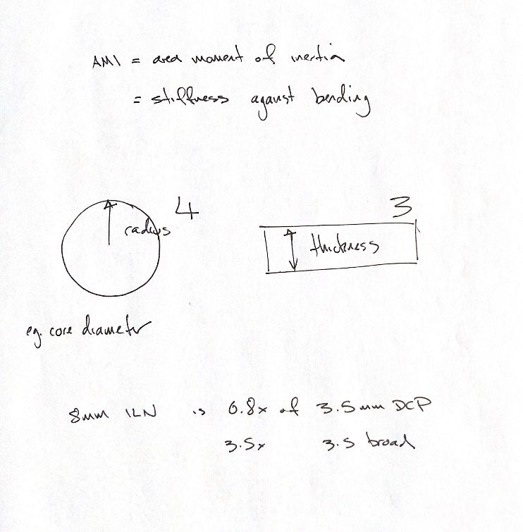
Area moment of inertia, or I, describes a cross-section's geometry for bending. Material also matters. Bending rigidity is E × I, where E is the material modulus. The stiffness of a whole implant or repair also depends on its working length and how it is supported.
For a solid round section, I rises with radius to the fourth power. For a rectangular section, I rises with thickness to the third power about the illustrated axis. Width and bending direction also matter. This is why small changes in pin or screw core diameter can make a large difference in bending behaviour.
Compare stated cross-sections. Table 41.5 lists I as 200.1 mm⁴ for the solid section of a regular 8 mm interlocking nail. Between screw holes, it lists 30.7 mm⁴ for a 3.5 mm DCP and 46.0 mm⁴ for a 3.5 mm broad DCP. Dividing these values gives about 6.5× and 4.4×. These ratios compare I; material, working length and fixation still affect the construct's stiffness.
The book's prose quotes 6.8× and 3.5× for that comparison. Those figures do not match the values in its table. The illustrated calculations use the listed table values so the sections and arithmetic are clear. The 3.5 mm plate name identifies its screw system; it does not give the plate's width or thickness. Holes also change I, and bending with or across a hole gives different values.
References
Johnston & Tobias, Veterinary Surgery: Small Animal, 2nd ed., Ch41, Table41.5 and accompanying text; MIT Unified Engineering, Handout M-13, Areas and Moments of Inertia (centroidal axes).