
Interlocking nail versus plate
Read the draft explanation
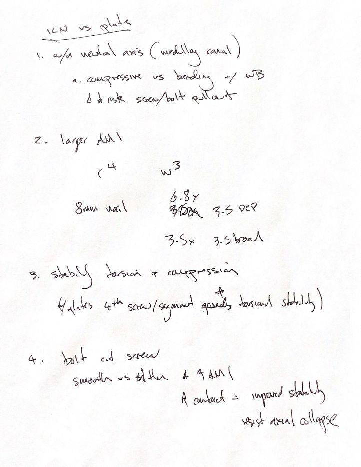
An interlocking nail sits near the bone's neutral axis, inside the medullary canal. This shortens the bending lever arm. During weight bearing, the nail tends to carry compression. A plate sits off to one side, so axial loading also creates a bending moment. That difference matters when a large fracture gap leaves the implant carrying the load.
Cross-section matters too. Area moment of inertia, or I, describes how material is spread around a bending axis. For a solid round nail, I rises with radius to the fourth power. For a rectangular plate at fixed width, it rises with thickness to the third power. Holes reduce I, and the bending direction changes the value at a nail hole.
The textbook's 8 mm solid-nail comparison gives about 6.8 times a 3.5 mm DCP and 3.5 times a broad 3.5 mm DCP. Those ratios differ from Table 41.5. Its values are 200.1, 30.7 and 46.0 mm⁴ for the solid nail and plate sections between holes. They give about 6.5 and 4.35 times. These are geometric values, not clinical strength multipliers.
Locking the nail to both main fragments controls torsion and resists axial collapse. In composite-bone LCP testing, adding screws increased torsional rigidity up to four per fragment. Moving the third or fourth screw did not change torsional rigidity in that model. The count is not a universal rule.
For regular nails, a smooth-shaft bolt has more central metal than a screw of the same outer diameter. Its larger I helps resist bending. Closer contact between nail and locking device reduces slack and improves stability. The intramedullary load path avoids the plate-type screw pull-out mechanism. Nail and bolt bending, breakage and instability can still occur.
References
Johnston & Tobias, Veterinary Surgery: Small Animal, 2nd ed., ch. 41, Tables 41.5–41.6 and Fig. 41.14; Stoffel et al., Injury 2003, doi:10.1016/j.injury.2003.09.021, discussion reproduced in Stoffel's 2007 UWA thesis, p. 87. Original ratios trace to Roe, ACVS Symposium 1998, pp. 436–437.