
Core and drill dimensions: master reference and eight recall prompts
Read the draft explanation
The size on a screw packet is the outer thread diameter. The core is the solid metal between the thread roots. They are different measurements.
The pilot drill prepares the hole that will hold the threads. In conventional lag technique, the wider glide hole lets the threads pass through the near cortex. A tap cuts the internal thread. A 3.5 mm tap names the matching screw thread; it does not mean you start with a 3.5 mm pilot drill.
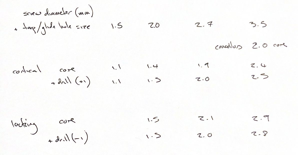
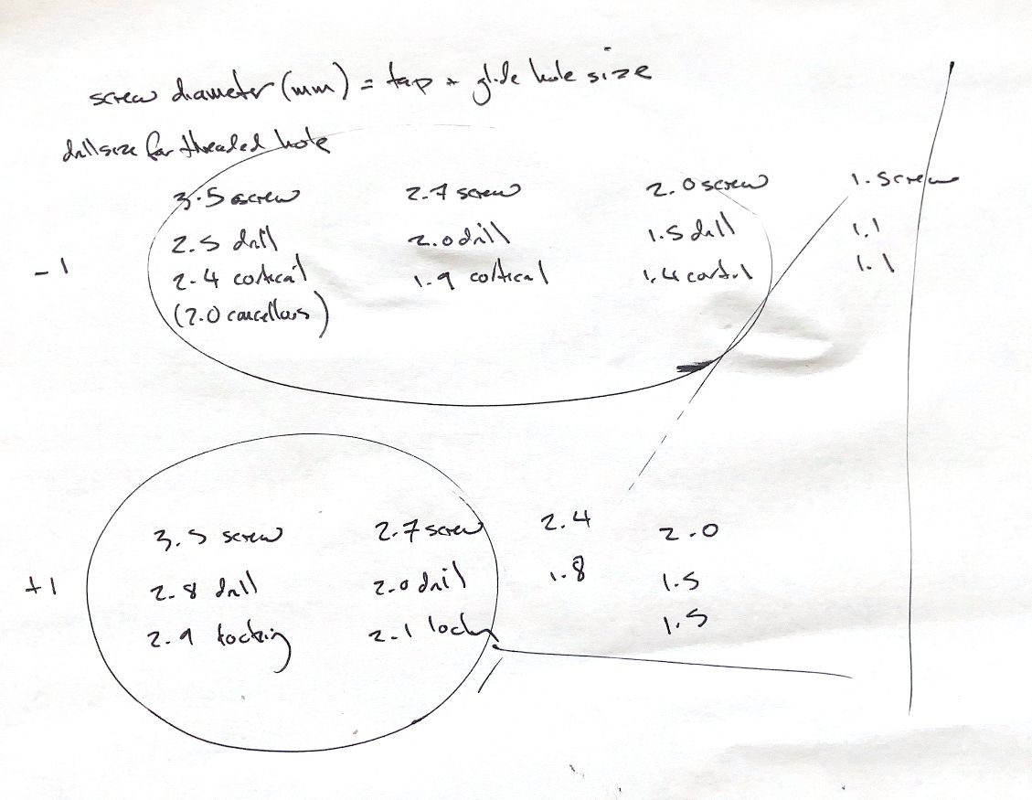
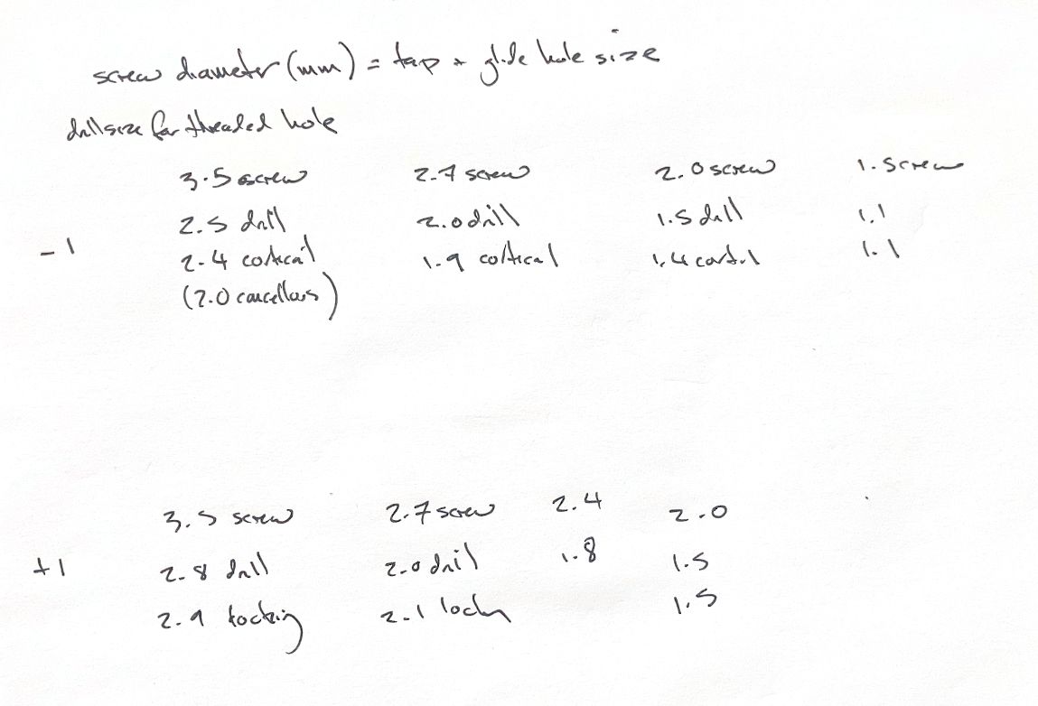
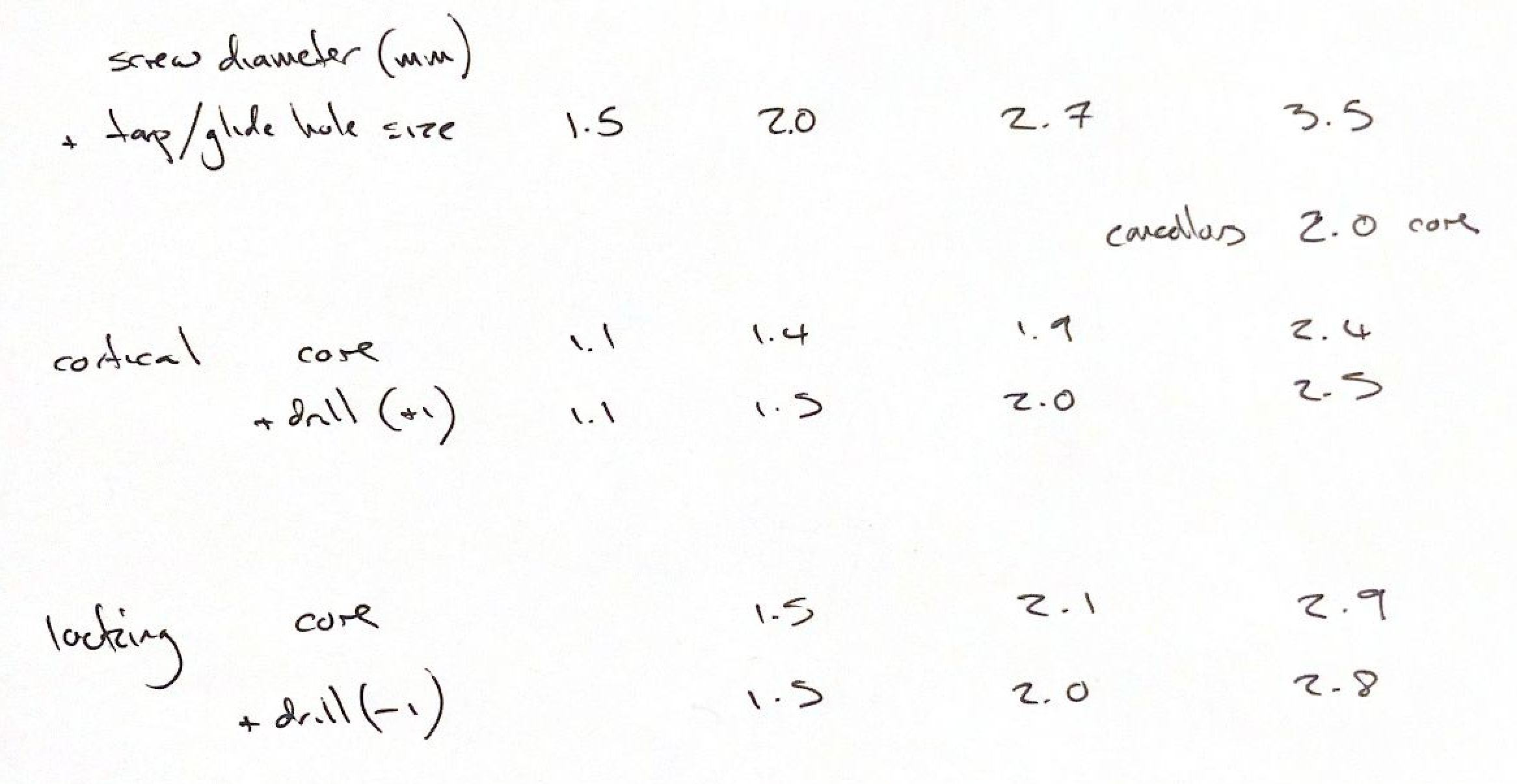
Read each table as screw size, core, then pilot drill. For the 2.0, 2.7 and 3.5 mm cortex screws shown, the pilot is 0.1 mm larger than the core. The 1.5 mm cortex example uses 1.1 mm for both. The old “minus one” cue works for 3.5 cortex to 2.5 drill, but it does not fit every row.
For the 2.4, 2.7 and 3.5 mm VS locking examples, the pilot is 0.1 mm smaller than the core. These are memory cues for these designs.
My notes list a 1.5 mm core for the 2.0 mm locking screw. The 2016 VS207 catalogue lists a 1.4 mm core, with the same 1.5 mm drill. That is the named design used in this table.
The 1.5 mm cortex core also varies: the older textbook figure shows 1.0 mm; the 2016 Synthes Vet designs shown here use 1.1 mm. And the classic 3.5 mm cancellous example has a 2.0 mm core. It is separate from the cortical and VS locking examples.
Learn the group, then check the actual system. The same nominal screw size does not guarantee the same core or drill.
References
Johnston & Tobias, Veterinary Surgery: Small Animal, 2nd ed., ch. 41, Figs. 41.19 and 41.22. DePuy Synthes Veterinary Product Catalogue (2016), pp. 2-1 to 2-4 and 2-8 to 2-9: https://www.jnjmedtech.com/system/files/pdf/DePuy%20Synthes%20Catalog.pdf