Calibration ball + side marker on EVERY radiograph.
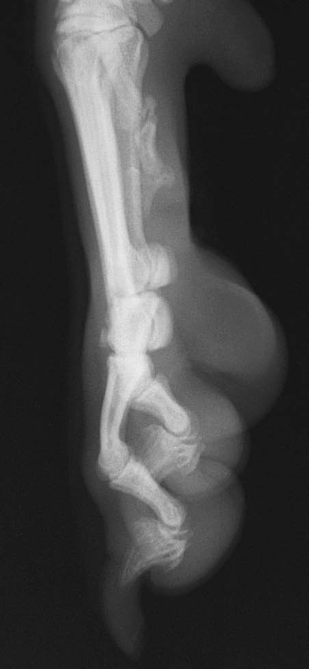
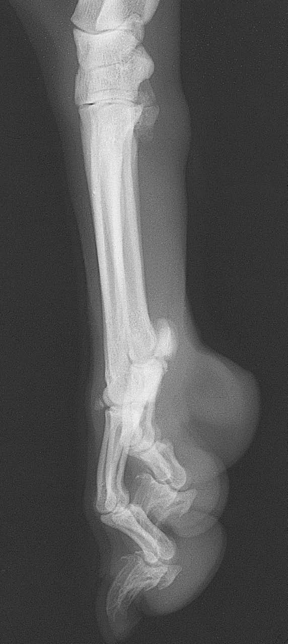
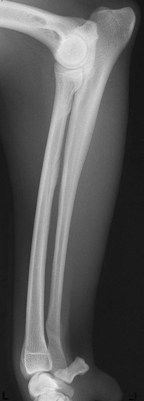
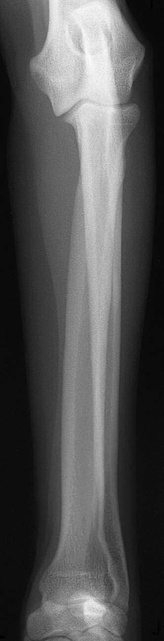
Normal dog examples. These show the projection and anatomy. Some atlas frames only partly show adjacent joints; use the coverage and image checks below for fracture studies. Include a calibration ball in every patient view, including when the atlas example has none.
VIEW 1
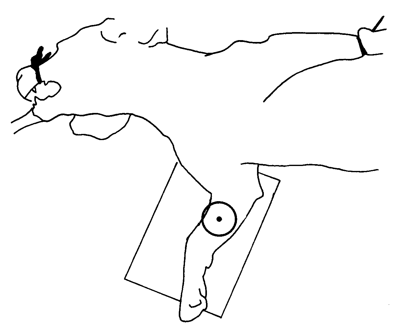
Mediolateral (side view)
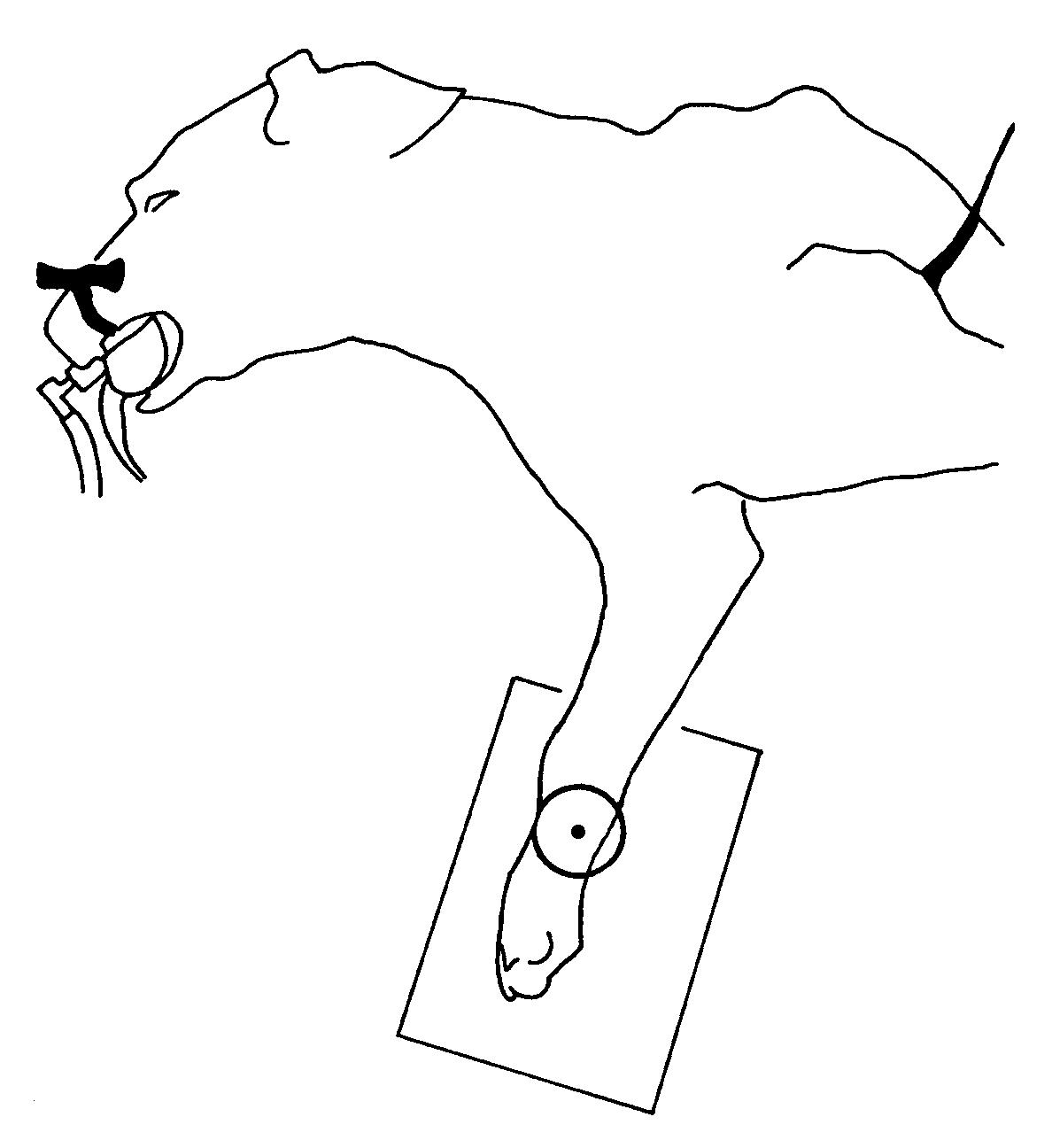
- Place the patient in lateral recumbency with the affected side nearest the detector. Support the forearm in a comfortable position away from the thorax.
- Keep the opposite forelimb clear. Use foam to support the limb without twisting the fracture.
VIEW 2
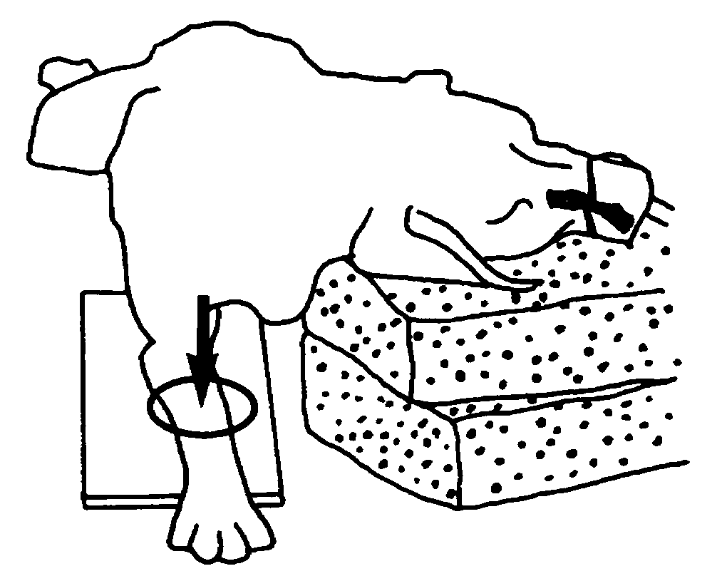
Craniocaudal (front view)
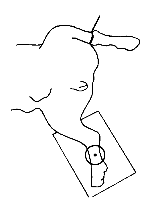
- If tolerated, use sternal recumbency with the affected forelimb supported cranially on the detector. Keep the carpus flat and the forearm straight.
- If that position is unsafe, coordinate a supported horizontal-beam alternative with the imaging team.
Beam centre and coverage
Centre over the middle of the radius/ulna. Include the entire radius and ulna, elbow and carpus, with surrounding soft tissues. An elbow-only or wrist-only view does not show the whole fracture region.
Check the images before sending
- Calibration ball visible in every radiograph.
- Two different projections, rather than two slightly rotated lateral images.
- Elbow and carpus included without cutting off either end of the bones.
- On the frontal view, assess rotation at both elbow and carpus; record any limitation caused by the injury.
Check patient ID, side marker, sharp cortical detail and soft-tissue exposure on both views. Send the original images with acquisition limitations noted.
Sources for radius / ulna
Coulson with Lewis, An Atlas of Interpretative Radiographic Anatomy of the Dog & Cat (2002). Dog pp 18-21, Figs 39-44 (PDF 28-31); cat pp 367-368 (PDF 377-378).
UF: elbow and antebrachium positioning plus the common acquisition references below. Normal alignment is a quality target where the injury permits, not a reason to force an injured limb.
Calibration ball + side marker on EVERY radiograph.
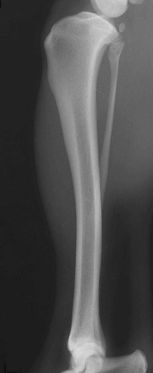
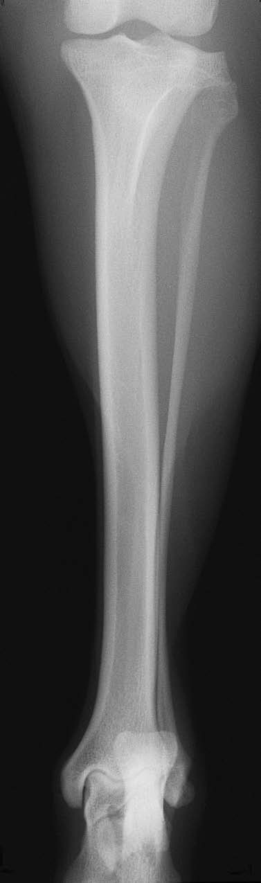
Normal dog examples. These show the projection and anatomy. Some atlas frames only partly show adjacent joints; use the coverage and image checks below for fracture studies. Include a calibration ball in every patient view, including when the atlas example has none.
VIEW 1
Mediolateral (side view)
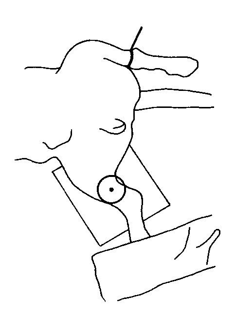
- Use lateral recumbency with the affected side nearest the detector. Move the opposite hindlimb clear of the tibia.
- Support the tibia parallel to the detector, with stifle and hock resting comfortably. Avoid imposing TPLO planning angles on a fracture patient.
VIEW 2
Frontal (craniocaudal or caudocranial)
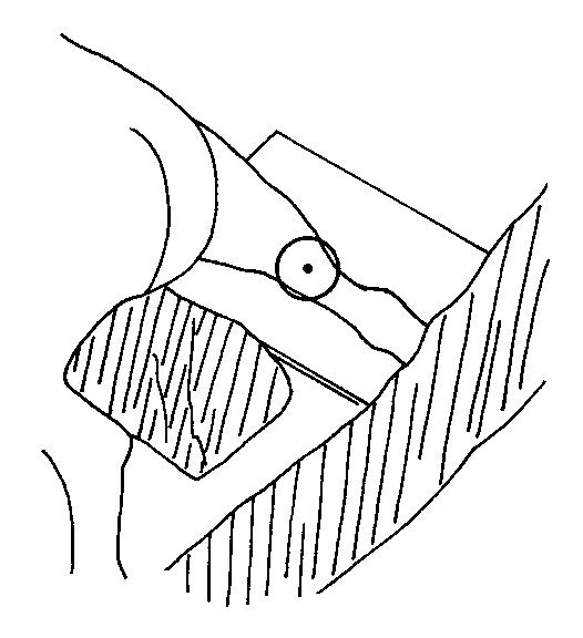
- Choose the projection and supported recumbency that the patient can safely tolerate. Dorsal recumbency can provide a CrCd view; a CdCr approach is an alternative.
- Align the tibia with the detector. A horizontal beam may help when repositioning is limited; coordinate the equipment and setup.
Beam centre and coverage
Centre over the tibial shaft for the whole-bone study. Include the entire tibia and fibula, stifle and hock, with surrounding soft tissues. Add joint-centred views if joint detail is needed.
Check the images before sending
- Calibration ball visible in every radiograph.
- Stifle and hock are present in both projections.
- Assess femoral-condyle superimposition on the lateral and patellar centring on the frontal view where injury permits.
- Displaced fragments may have different rotation; do not manipulate them to recreate a normal atlas image.
Check patient ID, side marker, sharp cortical detail and soft-tissue exposure on both views. Send the original images with acquisition limitations noted.
Sources for tibia / fibula
Coulson with Lewis, An Atlas of Interpretative Radiographic Anatomy of the Dog & Cat (2002). Dog pp 84-87, Figs 145-150 (PDF 94-97); cat pp 406-407 (PDF 416-417).
Mauragis & Berry: stifle and crus plus the common acquisition references below. Normal alignment is a quality target where the injury permits, not a reason to force an injured limb.
Calibration ball + side marker on EVERY radiograph.
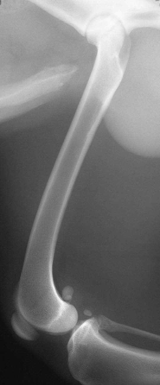
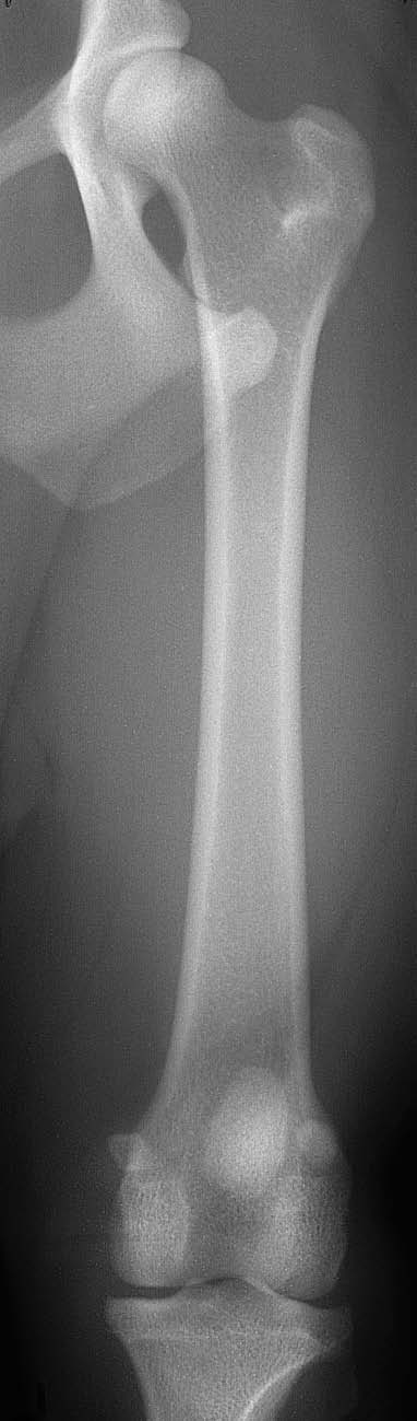
Normal dog examples. These show the projection and anatomy. Some atlas frames only partly show adjacent joints; use the coverage and image checks below for fracture studies. Include a calibration ball in every patient view, including when the atlas example has none.
VIEW 1
Mediolateral (side view)
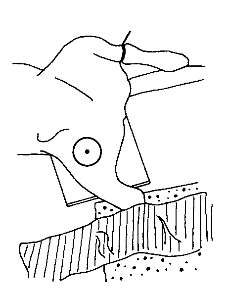
- Use lateral recumbency with the affected side toward the detector. Move the opposite hindlimb out of the femoral field.
- Support the patient and limb so the femur is as parallel to the detector as safely possible. Do not use traction to overcome pain or fragment displacement.
VIEW 2
Craniocaudal (front view)
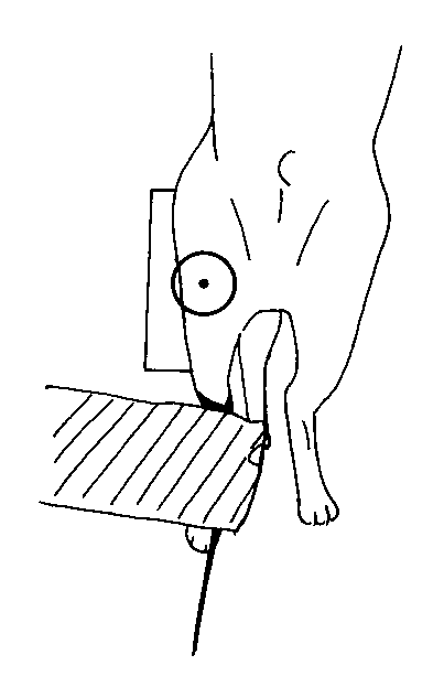
- Use a supported dorsal or slightly oblique body position to bring the femur into a frontal projection. Keep the hip and stifle in the image.
- Adjust patient support and detector orientation rather than forcing the injured limb into full extension. Coordinate an alternative if a true frontal view cannot be obtained.
Beam centre and coverage
Centre over the femoral shaft, between the hip and stifle. Include the entire femur, hip and stifle, with surrounding soft tissues. The full proximal femur must be visible rather than hidden behind the opposite limb.
Check the images before sending
- Calibration ball visible in every radiograph.
- Femoral head/neck and both ends of the femur are included.
- Check condylar superimposition on the lateral and patellar position on the frontal image, recognizing fracture displacement.
- The femur is not severely foreshortened or obscured by the opposite limb.
Check patient ID, side marker, sharp cortical detail and soft-tissue exposure on both views. Send the original images with acquisition limitations noted.
Sources for femur
Coulson with Lewis, An Atlas of Interpretative Radiographic Anatomy of the Dog & Cat (2002). Dog pp 74-77, Figs 124-129 (PDF 84-87); cat pp 400-403 (PDF 410-413).
Merck: general musculoskeletal positioning plus the common acquisition references below. Normal alignment is a quality target where the injury permits, not a reason to force an injured limb.
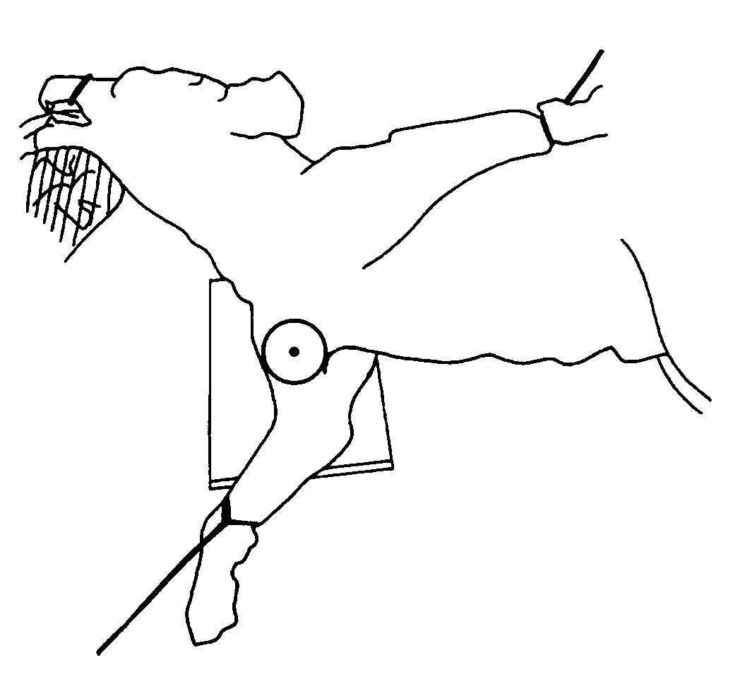
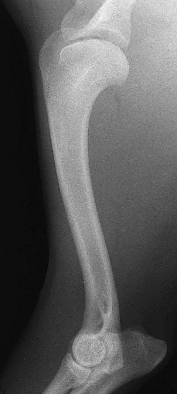
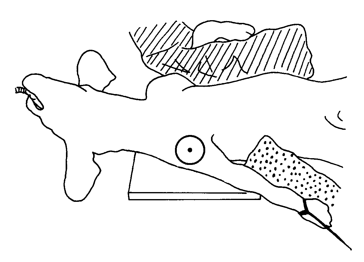
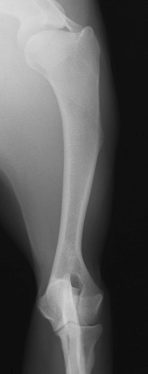
Calibration ball + side marker on EVERY radiograph.
Normal dog examples. These show the projection and anatomy. Some atlas frames only partly show adjacent joints; use the coverage and image checks below for fracture studies. Include a calibration ball in every patient view, including when the atlas example has none.
VIEW 1
Mediolateral (side view)
- Use lateral recumbency with the affected side toward the detector. Support the humerus away from the thorax as safely tolerated.
- Keep the opposite forelimb and sternum clear of the region of interest. Use padding to limit obliquity without twisting the injured limb.
VIEW 2
Frontal (craniocaudal or caudocranial)
- Use a supported body position that presents the humerus in a frontal projection. The atlas includes both CrCd and CdCr examples.
- Keep shoulder and elbow within the field. If the thorax obscures the shaft or the limb cannot be moved safely, coordinate a different setup.
Beam centre and coverage
Centre over the humeral shaft for the whole-bone study. Include the entire humerus, shoulder and elbow, with surrounding soft tissues. A routine shoulder or elbow study alone is insufficient for a shaft fracture.
Check the images before sending
- Calibration ball visible in every radiograph.
- Humeral head/shoulder and distal humerus/elbow are included.
- The shaft is visible without avoidable overlap from the chest or opposite forelimb.
- Check both views for additional fracture lines or fissures; do not assume a simple pattern from one image.
Check patient ID, side marker, sharp cortical detail and soft-tissue exposure on both views. Send the original images with acquisition limitations noted.
Sources for humerus
Coulson with Lewis, An Atlas of Interpretative Radiographic Anatomy of the Dog & Cat (2002). Dog pp 6-10, Figs 14-21 (PDF 16-20); cat pp 362-363 (PDF 372-373).
UF: humerus positioning plus the common acquisition references below. Normal alignment is a quality target where the injury permits, not a reason to force an injured limb.
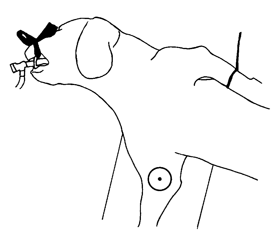
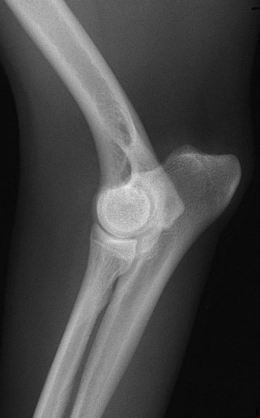
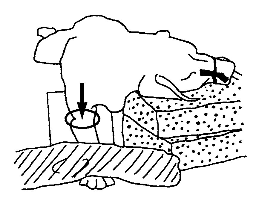
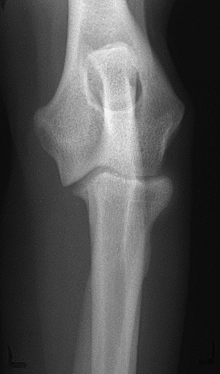
Calibration ball + side marker on EVERY radiograph.
Normal dog examples. These show the projection and anatomy. Some atlas frames only partly show adjacent joints; use the coverage and image checks below for fracture studies. These focused elbow examples supplement the full-humerus views. Include a calibration ball in every patient view, including when the atlas example has none.
VIEW 1
Elbow-centred mediolateral
- Use lateral recumbency with the affected elbow toward the detector. Support the forelimb in the position tolerated by the patient.
- Keep the opposite limb clear. Avoid routine forced flexion, extension or stress views of an unstable painful elbow.
VIEW 2
Elbow-centred craniocaudal
- If safely achievable, use supported sternal recumbency with the elbow and distal humerus on the detector.
- Use the intact proximal and distal anatomy to assess rotation; a displaced articular fracture will not reproduce normal symmetry. Coordinate a horizontal-beam alternative if needed.
Beam centre and coverage
Centre the focused pair over the humeral condylar / elbow region. For focused joint detail, include the distal third of the humerus and proximal third of the radius/ulna with all soft tissues. Also obtain full-humerus orthogonal coverage including the shoulder for fracture assessment.
Check the images before sending
- Calibration ball visible in every radiograph.
- The complete distal humeral articular region and both epicondylar areas are visible.
- Normal alignment checks help identify rotation, but displacement may prevent superimposition; do not force fragments to match.
- Discuss additional obliques or CT with the surgical service if the articular fracture pattern remains unclear. These are case-specific additions.
Check patient ID, side marker, sharp cortical detail and soft-tissue exposure on both views. Send the original images with acquisition limitations noted.
Sources for distal humerus / t-y fracture
Coulson with Lewis, An Atlas of Interpretative Radiographic Anatomy of the Dog & Cat (2002). Dog elbow pp 11-17, Figs 22-38 (PDF 21-27); cat pp 364-366 (PDF 374-376). These are normal-anatomy examples, not a T/Y fracture protocol.
UF: elbow positioning plus the common acquisition references below. Normal alignment is a quality target where the injury permits, not a reason to force an injured limb.
Calibration ball + side marker on EVERY radiograph.
Normal dog examples. These show the projection and anatomy. Some atlas frames only partly show adjacent joints; use the coverage and image checks below for fracture studies. Include a calibration ball in every patient view, including when the atlas example has none.
VIEW 1
Mediolateral (side view)
- Place the affected paw on its side and support the limb. Keep the opposite limb outside the field.
- Keep the paw close to the detector without forcing damaged digits to spread or the fracture to straighten.
VIEW 2
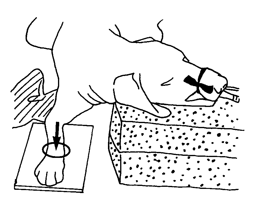
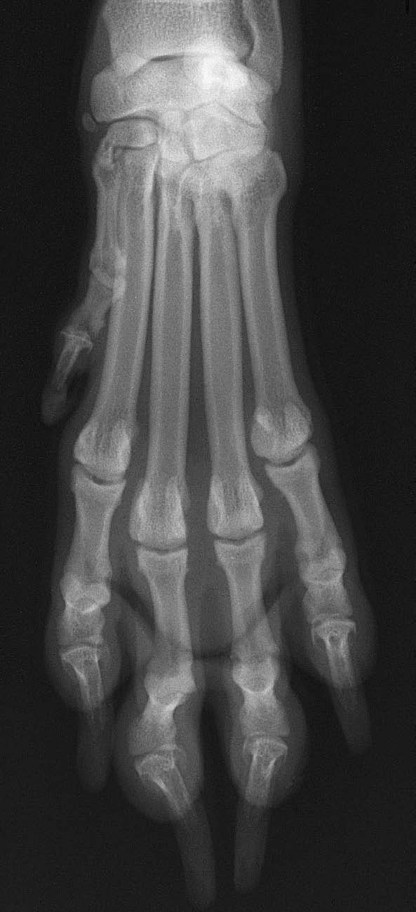
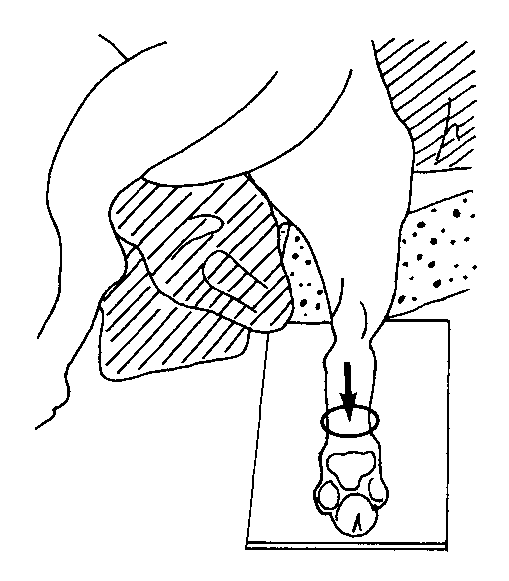
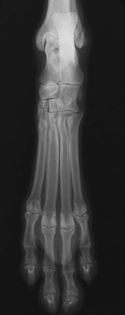
Frontal paw view
- Forepaw: dorsopalmar. Hind paw: dorsoplantar or plantarodorsal, according to the safely achievable setup.
- Support the paw flat to the detector and centre over the affected metacarpal/metatarsal region. Identify each injured bone and digit in the report.
Beam centre and coverage
Centre over the metacarpal or metatarsal region of interest. Include the full metacarpal/metatarsal bones from carpus/tarsus through the toes, including surrounding soft tissues and both ends of the injured bones.
Check the images before sending
- Calibration ball visible in every radiograph.
- The proximal bases, distal heads and relevant joints are not cut off.
- Lateral paw views normally superimpose several bones. Check whether each suspected fracture is actually visible.
- If overlap hides the fracture, coordinate supplemental oblique or focused digit views; do not treat a single lateral as adequate separation of every digit.
Check patient ID, side marker, sharp cortical detail and soft-tissue exposure on both views. Send the original images with acquisition limitations noted.
Sources for metacarpus / metatarsus
Coulson with Lewis, An Atlas of Interpretative Radiographic Anatomy of the Dog & Cat (2002). Dog manus pp 26-29 (PDF 36-39), hind paw pp 94-97 (PDF 104-107); cat manus pp 369-370 (PDF 379-380), hind paw pp 408-411 (PDF 418-421).
UF: carpus and manus; UF: tarsus and pes plus the common acquisition references below. Normal alignment is a quality target where the injury permits, not a reason to force an injured limb.

 View full screen ⤢
 View full screen ⤢
 View full screen ⤢
 View full screen ⤢